A hopping robot
Introduction

At the end of 2019 I built a 2kg hopping robot for a PhD researcher as part of a 6-week internship for the UCT Robotics Lab. When I joined the lab full-time I took over the project again and ported the system over to the Lab’s new Simulink Real-Time Target Machine using the CAN communication protocol, implemented impedance control, and built the Raibert-based control system for consistent hopping and velocity control. You can see the robot hopping and reacting to pushes in this video while it tries to stay in the same spot.
This video shows the first version of the hopper. I also built a newer version working part-time alongside my masters which used improved actuators, had stronger and more rigid legs, and a much simpler and lighter design.
Leg Impedance Control

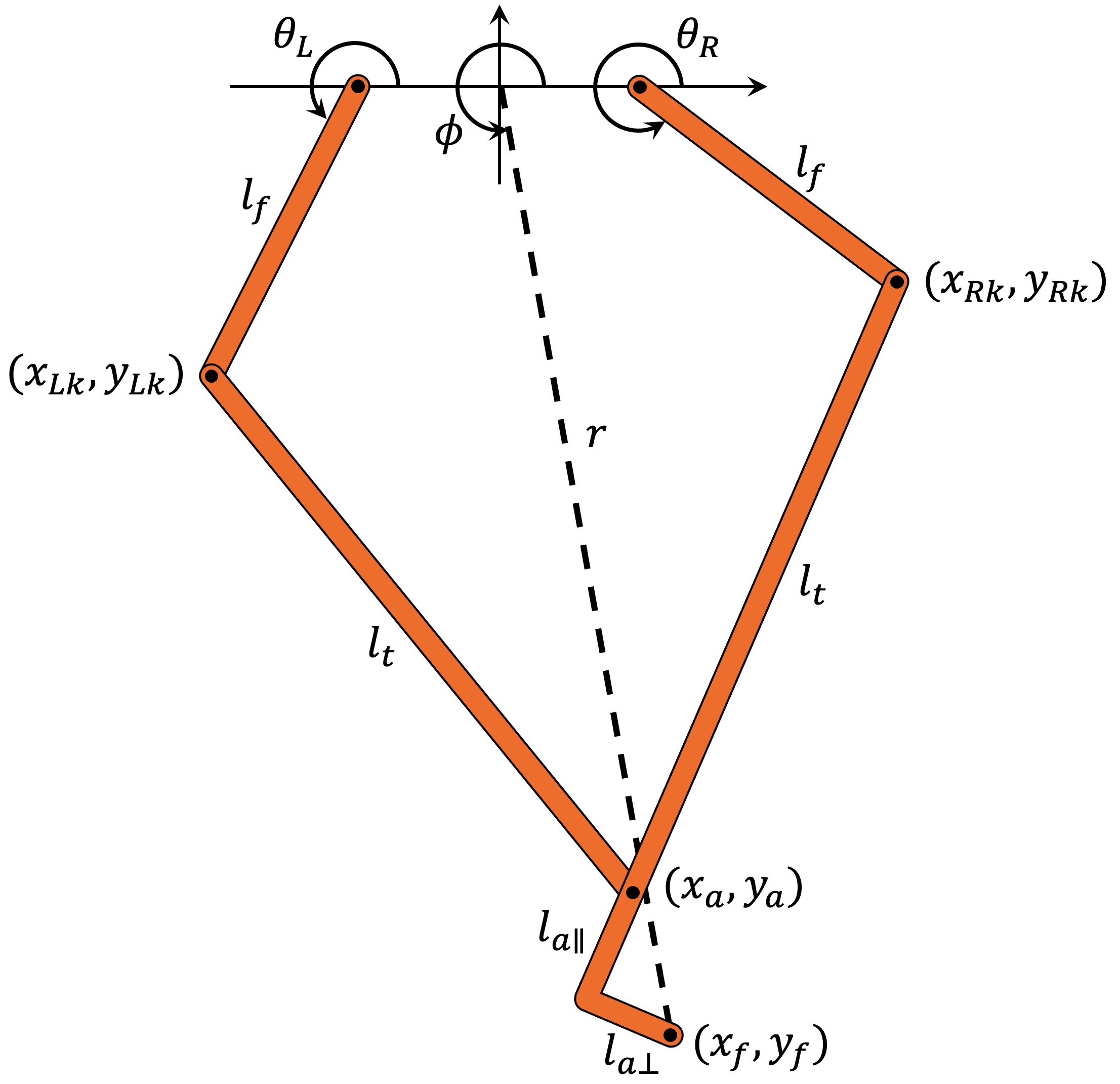
For dynamic robots like the hopper, controlling the force produced at the foot, and thus the body acceleration, is far more important than precisely controlling foot position. For this reason the leg is controlled with an impedance (force) controller in polar coordinates with a radial length \(r\) and an angle \(\phi\) from the body to the ankle, kind of like a pogo stick. Force in this polar frame is controlled by computing the required left \(\tau_L\) and right \(\tau_R\) motor torques from the desired radial force \(F_r\) and torque \(\tau_{\phi}\) using the leg polar Jacobian \(J_p\) calculated from the leg forward kinematics.
\[\begin{bmatrix} \tau_L \\ \tau_R \end{bmatrix} = J_p^T \begin{bmatrix} F_r \\ \tau_\phi \end{bmatrix}\]This ignores the mass and dynamics of the legs, but is still a reasonable approximation as the links are relatively light. A PD controller on each of the polar axes enables tracking of desired position and velocity setpoints \(r_0\), \(\phi_0\) and \(\dot{r}_0\), \(\dot{\phi}_0\).
\[F_r = K_p(r_0 - r_{leg}) + Kd_r(\dot{r_0} - \dot{r_{leg}}) + F_{thrust}\] \[\tau_{\phi} = Kp_{\phi}(\phi_0 - \phi_{leg}) + Kd_{\phi}(\dot{\phi_0} - \dot{\phi_{leg}})\]These PD controllers behave like a parallel spring and damper where \(Kp\) is the spring stiffness with units \(\frac{N}{m}\) or \(\frac{Nm}{rad}\) and \(Kd\) is the damping constant with units \(\frac{Ns}{m}\) or \(\frac{Nms}{rad}\). The radial stiffness determines how much the leg compresses during landing. Higher jump heights will need higher radial stiffness to stop the leg bottoming out (think pogo stick). The polar angle stiffness determines how quickly the leg repositions during flight. The damping constants are typically set to keep the axes more or less critically damped and avoid any oscillations.
Enjoy Reading This Article?
Here are some more articles you might like to read next: